
|

|
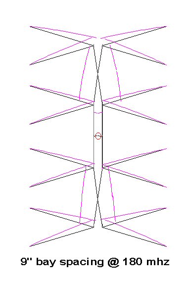
| The
above diagram is showing the current distribution at near a
half
wave for a 9" bay spacing. As can be seen the current is very close to
the same on the inner and outer elements but the outer elements are
just slightly out of phase as can be seen by the little dip in current
just after the whisker / phase line junction. |
The
above diagram is showing the current distribution at well
above a
half wave for a 9" bay spacing. here you can see the elements are all
out of phase to a certain degree with the outer bays being a bit
further out than the inners. |
 |
|
| The
above diagram is showing the current distribution at well
below a
half wave for a 9" bay spacing. Here you can see the outer bays are
more in phase than the center 2 and the current distribution is a bit
unbalanced between bays. It's still not enough to cause signal
cancellation between bays, but they are not all working perfectly
together. |
The
above diagram is showing the current distribution at VHF-HI
frequencies for a 9" bay spacing. You can see here we are
getting
no where near a full current lobe on any element and the outer 2 seem
to be carrying most of the load. Most of the current lobe is running up
the phase line with the remainder coming out the whiskers mainly on the
top and bottom bays. Luckily not much current is flowing in the center
bays since these would be way out of phase with the outers causing some
cancellation. |
I
enhanced the current flow on these diagrams to better show the lobes so
some examples may be showing slightly larger lobes than others. On UHF
because
of the distance difference between the inner and outer bays all 4 are
never quite in phase at the same time but are very close and
there will be times when one is slightly out and the other is on and
visa versa. There will also be times where they are all out of phase as
compared to the wavelength but the inner and outers still remain quite
close to each other. On VHF-HI it's a much different story it
appears the antenna behaves more like stacked inverted L antennas with
the center 2 whiskers acting mostly as loading lines and not
adding much to the radiation of the antenna.
|
|
|
|
|
|
|